Seven-Segment Display
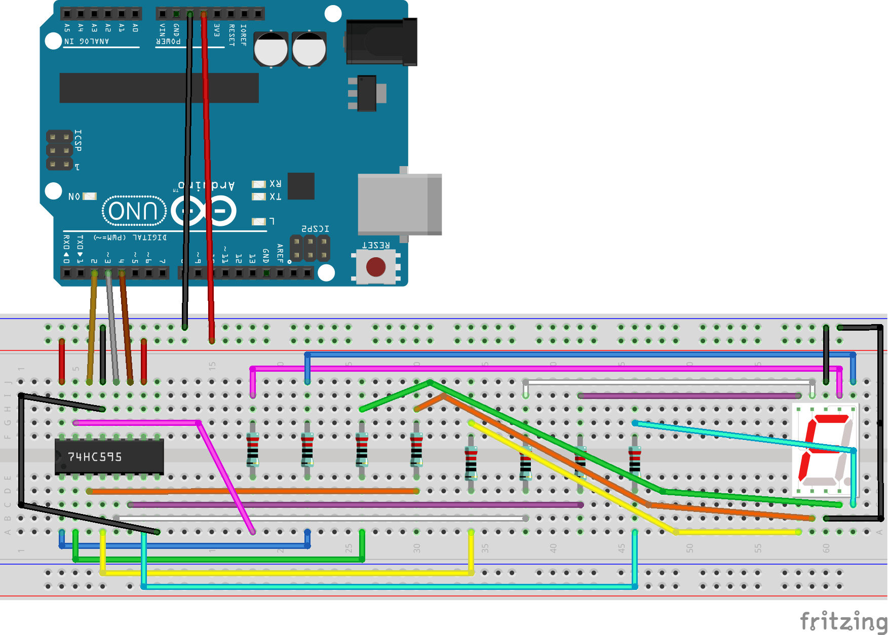
This project took quite a while to make, primarily due to the complexity of identifying the function of each pin on the 10-pin display module. I relied on browsing forums and having discussions with others with similar issues to map the correct pin configuration and thus get the device working. The video above demonstrates the system counting down from 9 to 0 at one-second intervals, followed by the display of the number 3. The corresponding code and the diagram are below.
// Byte array for each digit
byte seven_seg_digits[10] = {   B11111100, // = 0
                                B01100000, // = 1
                                B11011010, // = 2
                                B11110010, // = 3
                                B01100110, // = 4
                                B10110110, // = 5
                                B10111110, // = 6
                                B11100000, // = 7
                                B11111110, // = 8
                                B11100110  // = 9
                            };
const int latchPin = 3;
const int clockPin = 4;
const int dataPin = 2;
For this project, a byte array is needed for
each digit's data. There are also three pins required for the IC to interact with the
Arduino. All three are initialized as outputs with the
pinMode() method.
for (byte digit = 10; digit > 0; digit--) {
    delay(1000);
    sevenSegWrite(digit-1);
}
delay(3000);
sevenSegWrite(3);
All digits from 9 - 0 are printed on the display using the for-loop. After, the
number 3 is written to the display. I made a custom method called
sevenSegWrite()
that takes in an integer as a parameter in order to display numbers, shown below.
void sevenSegWrite(byte digit) {
    digitalWrite(latchPin, LOW);
    shiftOut(dataPin, clockPin, LSBFIRST, seven_seg_digits[digit]);
    digitalWrite(latchPin, HIGH);
}
Here, dataPin takes the output on pin 2 for the IC,
clockPin is the pin is toggled, and
LSBFIRST describes the order in which to read the bits.
LSB stands for least significant bit, meaning data processing starts from the bit with the lowest
binary place value (typically the rightmost bit). For the last parameter, the
byte value stored in the array corresponding to
the desired digit is sent.