Motor Circuit
In the demo, the motor rotates left for 8 seconds, rotates right for 8 seconds, then alternates between rotating left and right 10 times. Finally, the motor then spins one more time to the left.
// Three constants give the direction and speed for the motor
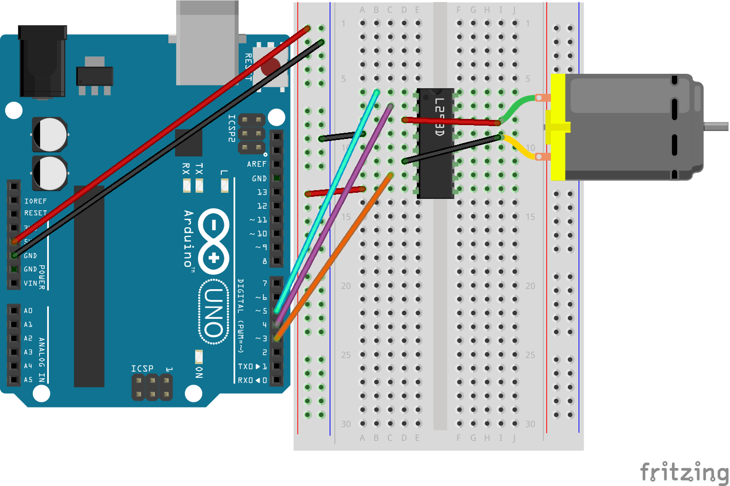
const int enablePin = 5;
const int dirA = 4;
const int dirB = 3;
In this project, I used three constants throughout the code for readability. The values set for
each variable match to the respective pin connected to the Arduino (see diagram at bottom). All
three pins are initialized as outputs in the
setup() method.
for (i = 0; i < 5; i++) {
    digitalWrite(dirA, HIGH);
    digitalWrite(dirB, LOW); delay(500);
    digitalWrite(dirA, LOW);
    digitalWrite(dirB, HIGH); delay(500);
}
The code above drives the motor to alternate directions at a fixed interval, rotating
in one direction for 0.5 seconds before reversing for another 0.5 seconds. This is done through the
digitialWrite() method, which sets pin to either
HIGH or LOW.
for (int i = 50; i > 255; i += 50)
    analogWrite(enablePin, i); delay(2000);

for (int i = 255; i > 55; i -= 50)
    analogWrite(enablePin, i); delay(2000);
Here, the first for-loop gradually ramps up the motor speed, while the second one incrementally reduces it.
The, analogWrite() function is used to achieve variable speed control via
pulse width modulation (PWM), as opposed to digitalWrite() which only accepts
binary values (HIGH and LOW).
Since digitalWrite() can only toggle the motor on
or off, it does not allow for intermediate speed control. The L293D is a motor
controller IC that enables this functionality by allowing directional control and PWM-based speed modulation for DC
motors.